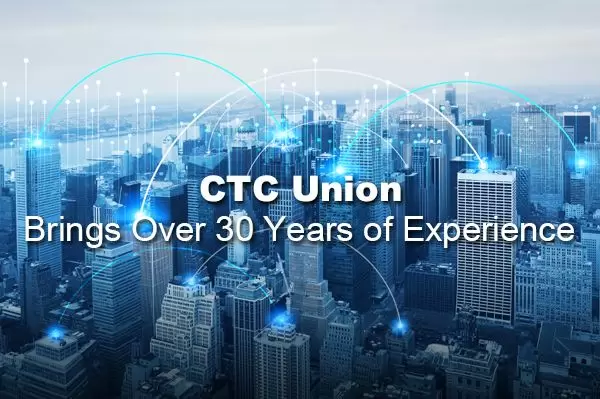
CTC Union Technologies Co., Ltd. | Founded in 1993, CTC Union partners with voice and data carriers, enterprises, and industrial grade Ethernet users covers all continents and areas.
CTC Union's goal is to provide reliable, temperature resistant and rugged designs for harsh environments. We offer a full spectrum of products, including L3/L2 Switch, PoE Products, EN50155 and E-Mark certified switches. CTC Union is a leading Taiwanese manufacturer specializing in telecommunication products such as L2 Ethernet switches, transponders, and industrial Ethernet switches, converters, and injectors. The company maintains strict control over product design, ensuring compliance with certifications like CE, FCC, UL, IEC 62443-4-1, EN50155, EN45545-2, and IEC61850-3. CTC Union has established strong global partnerships with voice and data carriers, enterprises, and industrial Ethernet users, providing direct engineering and technical support from its headquarters in Taipei, Taiwan.
Company Fact In Numbers
0
Years of Experience
0
Product Category
0%
Customer Satisfaction
Hot Products
We'll show you 4 hot products in 2026, and they've got to be profitable products that will earn you a good margin.
The next generation Ethernet switch featuring high-density ports leverage NBase-T multigigabit technology, enabling network upgrades from 1Gbps to 2.5Gbps speeds.

Spotlight
Welcome to the CTC Spotlight! You'll find everything you need to know - from product news and company events to product reviews, promotion materials, and more.

e-Newsletter
Latest Product & Company NewsStay up to data on our latest news
CTC Union e-Newsletter Issue No.3, 2026
CTC Union Cordially Invites You to COMPUTEX 2026 and Key Product Promotion (Cyber Hardened L3 Routing Switch & Serial Optical Repeater)
Highlight Product
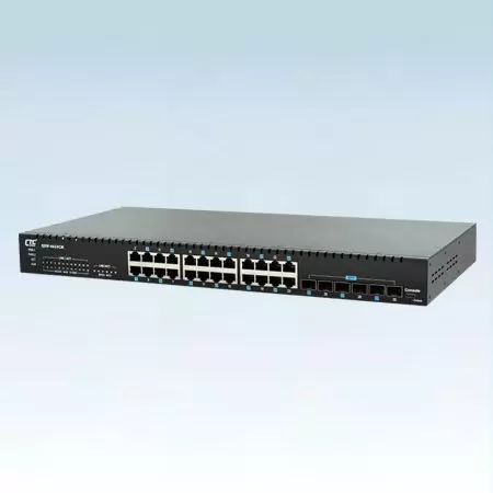
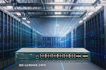
L3 10G Ethernet SwitchIXR-G24044X-24PH delivers resilient, high-speed networking with 4×10G uplinks and 24×GbE PoE ports — powering dense, multi-site industrial automation networks.
Media Center
Corporate VideoCTC Union will continue to develop an unmatchable network transmission. Shaping the future of better connectivity.
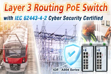
Featured Product
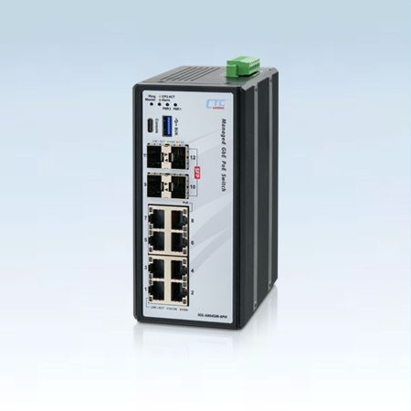
IGR-A804 SeriesThe IGR-A804 Series supports fan-less operation, wide temperature tolerance, 4KV surge protection, and redundant 48VDC power input — ideal for industrial automation, transportation, utilities, and critical infrastructure applications.